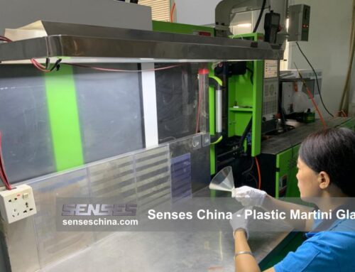
In the injection molding, the quest for perfection is an ongoing battle against a myriad of potential defects that can compromise the quality, functionality, and aesthetics of the final product. The process, while highly efficient and versatile, is susceptible to a variety of issues ranging from material-related challenges to equipment and process parameter variations. Each defect tells a story about the conditions it was born from, and understanding these narratives is key to crafting effective solutions.
Let’s expand on the list of common injection molding defects and their solutions with more detail and additional examples:
1. Short Shot (Incomplete Fill)
Short Shot, also known as Incomplete Fill, is a common defect in the injection molding process that results in a partially formed or undersized part. This defect not only affects the functionality and structural integrity of the final product but also leads to production delays and increased costs. It occurs when the molten plastic fails to completely fill the mold cavity. The causes of short shots can be multifaceted, involving factors such as material properties, mold design, processing conditions, and equipment performance.
Solutions to Short Shot:
-
- Increase Injection Volume: Ensuring that there is enough material to fill the mold completely.
- Improve Material Flow: This can be achieved by increasing the temperature of the material to reduce its viscosity, allowing it to flow more easily into the mold.
- Optimize Injection Speed and Pressure: Proper injection speed and pressure can help the material to reach all areas of the mold.
- Mold Temperature Control: Uniform and appropriate mold temperatures can improve material flow and reduce the likelihood of short shots.
- Gate and Runner Design: The design of the gate and runner system can affect the flow of material into the mold. Ensuring that the gate is properly sized and positioned can help prevent short shots.
- In-Process Monitoring: Implementing real-time monitoring and quality control measures can help detect deviations before they result in defects, allowing for adjustments to be made on the fly.
2. Warping (Distortion)
Warping, or distortion, in injection molding arises from a complex interplay of factors that affect the final shape and stability of the molded part. One primary cause is the uneven molecular orientation during the molding process, where the polymer chains align more in the flow direction than perpendicular to it, leading to differential shrinkage rates and consequent warpage.
Another significant factor is improper cooling, which, if not uniformly distributed across the mold, can result in inconsistent material contraction and warping, especially pronounced in parts with varying wall thicknesses. The design of the mold gate system also plays a crucial role; an ill-conceived gate can induce uneven material flow and stress distribution within the part, contributing to warpage.
Furthermore, the mold ejection and venting system design must ensure balanced forces during part removal to prevent warpage due to mechanical distortion. Lastly, processing errors such as insufficient injection pressure, slow injection speed, inadequate packing time, and improper material drying or annealing can exacerbate the warping issue.
Solutions to Warping:
-
- Adjust Mold Temperature: Lowering the mold temperature or extending the cooling time can help reduce warpage, especially for long and slender parts.
- Improve Cooling Uniformity: Enhancing the mold’s cooling system to ensure even cooling of the part is essential.
- Optimize Gate Design: Selecting the appropriate gate type based on the specific conditions can help minimize warpage.
- Check for Mold Core Shift: Inspection and correction of any mold core shift can prevent warpage caused by uneven forces during ejection.
3. Bubbles (Entrapped Air or Moisture)
Bubbles in injection molding are mainly caused by trapped air and moisture. Inadequate venting in the mold prevents the escape of air, while the presence of moisture in the plastic can vaporize during molding. High injection speeds and pressures can also entrap air within the melt. Additionally, improper mold and material temperatures, insufficient back pressure, and the screw design of the injection unit can contribute to air entrainment.
Solutions to Bubble Formation:
-
- Improve Mold Venting: Ensuring that the mold has adequate vents can allow trapped air and gases to escape.
- Proper Material Drying: Using a dehumidifying dryer or drying the material to the recommended moisture level before molding can prevent moisture-related bubbles.
- Adjust Injection Parameters: Reducing injection speed and pressure can help minimize air entrapment.
- Optimize Mold and Material Temperatures: Setting appropriate mold and melt temperatures can facilitate the escape of air and prevent bubble formation.
- Increase Back Pressure: Raising back pressure can help to remove entrained air from the melt.
- Screw Design and Maintenance: Ensuring the screw is designed to minimize air entrainment and is well-maintained can reduce the risk of bubbles.
- Mold Design Modifications: Simplifying the mold design or adding additional vents can improve air escape and reduce bubble formation.
- Material Selection: Choosing materials that are less prone to outgassing or have lower moisture absorption can help prevent bubbles.
4. Silver Streaks (Melt Fracture)
Silver streaks, or melt fracture, in injection molding are typically characterized by elongated, silver-white lines on the surface of the molded part, often emanating from the gate in a fan-like pattern. This defect is primarily caused by the volatilization of moisture or other volatile substances within the plastic material during the molding process, which can lead to the formation of surface bubbles. Additionally, the phenomenon of melt fracture occurs when the shear rate of the polymer melt surpasses a critical threshold, causing the polymer chains to align and create a rough, irregular surface.
Processing conditions, such as excessively high injection speeds or improper temperature control, can exacerbate this issue, as the material may not have sufficient time to relax between the shear forces applied. Mold design also plays a critical role; poor venting can trap air, while certain gate designs may not facilitate the smooth flow of material, contributing to silver streaks. Furthermore, the material’s inherent properties, including molecular weight distribution and the presence of additives, can influence its susceptibility to melt fracture.
Solutions to Silver Streaks:
-
- Proper Material Drying: Ensuring that the plastic material is adequately dried before molding to remove moisture and other volatiles can help prevent silver streaks.
- Optimize Processing Parameters: Adjusting injection speed, temperature, and pressure to avoid conditions that induce melt fracture is crucial.
- Improve Mold Design: Enhancing mold venting and modifying浇口 design to facilitate the escape of air and reduce the occurrence of silver streaks.
- Material Selection: Choosing materials with lower melt fracture tendencies or using additives that can improve melt stability.
5.Weld Lines (Knit Lines)
These are visible lines or seams that occur when two or more fronts of molten plastic meet within the mold cavity and fail to fuse completely, creating a weak point in the part’s structure that can also affect its appearance. The formation of weld lines is influenced by various factors, including the part’s geometry, which dictates how plastic flows around mold obstructions and converges, leading to the weld line. The mold design, particularly the gate and vent configurations, plays a critical role in determining where weld lines form, as does the material’s properties, including the presence of additives or reinforcements that can impede the fusion of melt fronts. Processing parameters, such as injection speed, pressure, and temperature, also contribute to weld line formation by affecting the cooling rate and the melt’s ability to merge.
Solutions to Weld Line Formation:
-
- Part Design Optimization: Modifying the part design to minimize the convergence of flow fronts, such as by adjusting the location of holes or adding ribs for strength, can help reduce weld lines.
- Mold Design Adjustments: Ensuring proper gating and venting to facilitate material flow and minimize the angle at which flow fronts meet can mitigate weld line formation.
- Material Selection: Choosing materials with good weld line integrity or adjusting the material composition to improve the ability of the melt fronts to fuse together.
- Processing Parameter Adjustments: Optimizing injection speed, pressure, and temperature to ensure adequate time for the melt fronts to merge and solidify.
6.Sink Marks (Shrinkage)
Sink Marks, also known as shrinkage marks, are depressions that occur on the surface of a molded part due to variations in cooling rates during the solidification phase. The formation of sink marks is influenced by several factors including part geometry, material selection, mold cooling, injection parameters, and volumetric shrinkage. Thick ribs or sections in the design can exacerbate the issue if they are not proportionate to the wall thickness, while certain polymers with high filler content or low melt flow rates are more prone to shrinkage due to their viscosity and cooling characteristics. Uneven or insufficient cooling within the mold can also lead to premature solidification in some areas, and inadequate packing pressure or insufficient cooling time during the injection process can compound the problem.
Solutions to Sink Marks:
-
- Optimize Part Design: Reducing the thickness of ribs and ensuring uniform wall thickness can help prevent sink marks.
- Improve Mold Cooling: Enhancing the cooling system in the mold, especially in areas opposite thick sections, can help reduce sink marks by promoting even cooling.
- Select Appropriate Material: Choosing materials with lower viscosity and faster cooling rates can reduce the likelihood of sink marks.
- Adjust Injection Parameters: Increasing packing pressure and extending cooling time can help minimize sink marks by allowing material to flow out and fill any gaps before solidification.
- Control Volumetric Shrinkage: Proper holding pressure and time can prevent volumetric shrinkage that leads to sink marks.
7. Flash (Extrusion)
Flash, or extrusion in injection molding, emerges when thin protrusions of plastic material are forced beyond the mold’s parting line, typically due to excessive pressure or an imperfect mold fit. Over time, mold wear can exacerbate this issue by enlarging these gaps. The injection pressure itself, if set too high, can also push the molten plastic out of the mold cavity, especially in areas with less resistance. The design of the parting line plays a crucial role; if it is not carefully planned, it can lead to stress concentrations and flash formation. The choice of material can also influence the likelihood of flash, with some materials being more prone to extrusion due to their flow characteristics. Additionally, the positioning of the gate and the design of the ejection system can contribute to flash if they do not facilitate smooth and even part ejection.
Solutions to Flash:
-
- Ensure Proper Mold Closure: Regular maintenance and inspection of the mold to ensure tight closure and adjust clamping forces as needed.
- Mold Maintenance: Regularly check for and address any signs of mold wear to minimize gaps at the parting line.
- Adjust Injection Pressure: Lowering injection pressure to a level that fills the mold without extruding material can help reduce flash.
- Optimize Parting Line Design: Designing the parting line to minimize stress concentrations and ensuring even pressure distribution can help prevent flash.
- Material Selection: Choosing materials with appropriate flow properties for the molding process can reduce the likelihood of flash.
- Gate Location Optimization: Positioning the gate away from the parting line can minimize the risk of material leakage.
- Improve Ejection System: Ensuring that the ejection system applies even forces and does not cause additional stress on the part can help to prevent flash.
8.Adhesion (Mold Release Issues)
Mold adhesion in injection molding, characterized by parts sticking to the mold and causing ejection issues, stems from a variety of factors. The condition of the mold surface plays a pivotal role; a lack of sufficient polish or presence of porosity can increase the part’s grip on the mold through mechanical interlocking and chemical bonding. The choice of material can also influence adhesion, with certain plastics exhibiting a greater affinity for the mold’s surface. Improper application of mold release agents, whether uneven or insufficient, fails to create an effective barrier, leading to part sticking. Process parameters, such as excessively high injection pressure or mold temperature, can also intensify the adhesion strength. Mold design features, like sharp corners or undercuts, can impede part release by increasing the resistance against ejection. Contaminants in the material, such as dust or mixed grades, can cause sticking, as can poor venting design that results in air trapping and localized overheating.
Solutions to Mold Release:
-
- Improve Mold Surface Finish: Enhancing the mold’s polish and filling any porosity with appropriate sealers can create a smoother, more chemically inert surface that is less prone to adhesion.
- Optimize Material Selection: Choosing materials that are less likely to adhere to the mold surface or using additives that improve release properties.
- Proper Mold Release Application: Applying the right type and amount of mold release agent consistently and evenly to create an effective barrier between the mold and the part.
- Adjust Process Parameters: Fine-tuning injection pressure, melt temperature, and mold temperature to minimize adhesion without compromising part quality.
- Mold Design Improvements: Modifying the mold design to include features that facilitate part release, such as proper draft angles, radii, and venting.
- Maintain Material Purity: Ensuring that the material is free from contaminants and is uniformly dried and processed.
- Enhance Mold Venting: Improving the venting design to allow trapped air to escape and prevent localized overheating.
Senses: Your Partner in Injection Molding Solutions

Senses is an ISO 9001:2015 certified plastic injection molding company, offering a comprehensive array of services including mold and part design, prototyping, small-batch production, and full-scale manufacturing. We serve a diverse range of industries, encompassing automotive, medical, and consumer electronics. Our focus is on ensuring each product we deliver meets the highest standards of quality and functionality.
For personalized solutions and expert consultation, reach out to us today at info@senseschina.com.

