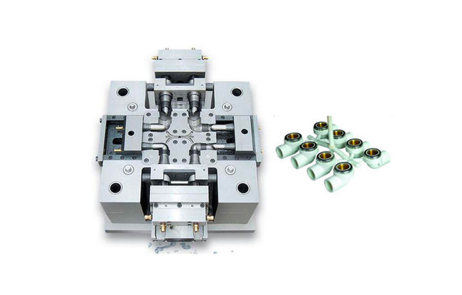
A gate is a designed small opening to allow the melted plastics into the mold cavity, a successful gate design is determined by gate type, dimensions, location, it’s deeply related with the materials been used, the type of mold plates, and economic factors. Gate design is one of the most important elements to influence injection mold quality and productivity.
There are two categories of Gate for injection moulding:
Manually Trimmed Gates: require an operator to separate parts from runners during a secondary operation.The reasons for using manually trimmed gates are:
- Simultaneous flow distribution across a wide front to achieve specific orientation of fibers of molecules often precludes automatic gate trimming.
- Some shear-sensitive materials should not be exposed to the high shear rates inherent to the design of Automatically trimmed gates.
- The gate is too bulky to be sheared from the part as the toop is opened
These gate types need to be trimmed from the cavity manually:
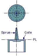
Direct sprue gate – used in the case of single-cavity or when putting the gate direct to the base of the injection-molded product. Residual strain tends to occur because the injection pressure will directly apply to the molded product, but its mold construction is most simple, this type of gate is normally for the none appearance part surface.
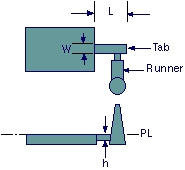
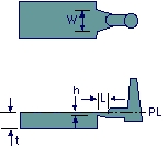
Tab gate – this is a method that sets up a tab on the side of the molded product, and the gate is placed there. Commonly, the gate and the tab should be fixed at a proper angle. Gate allowance will allow on the gate separate, so overcome balance strain and movement marks under the tab are available, after molding this tap will be cut off by manual.
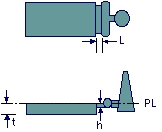
Side gate – this type is the most generally adopted and used well in multi-cavity molds. Its shape is rectangle or semicircle and placed at the side of the molded product, this is normal gate which used for the molded parts,
Fan gate – its structure is similar to the side gate, but the gate width is bigger and fan-shaped. Used in large size molded products, this type of gate is normally for the clear injection molding parts, such as PMMA injection molding parts, PC injection molding parts or any other transparent clear plastic molding parts, the reason this type of gate is easy to mold the good surface, but the disadvantages are this type gate is hard to trim off, must use some special tool or laser cutting process.
Film gate – this type will be applied to the plate-shaped molded product. This type is effective to prevent deformation by suppressing strain.
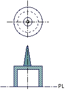
Disk gate – this gate is used to prevent eccentricity and weld when molding disk or cylinder-shaped products, however, there is a disadvantage in that the finishing of the gate part is difficult.
Automatically Trimmed Gates: incorporate features in the tool to break or shear the gate as the molding tool is opened to eject the part. Automatically trimmed gates should be used to:
- Minimize gate scars.
- Maintain consistent cycle times for all shots
- Avoid gate removal as a secondary operation
These gate types will be trimmed from the cavity automatically:
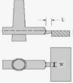
Pinpoint gate – diameter of the pinpoint gate is between 0.5mm to 2mm, and as an advantage, it does not need any finishing. Gate allowance is fast and pressures that because balance strain will not join to the molded stock. If the gate cross-sectional areas are small, flow distance will decrease and flow marks tend to occur around the gate, this type of gate is normally for the multiple cavity small parts, like 16 cavity or 24 cavity molds, when you use this type of gate then we normally call this mold as 3 plate mold.
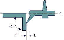
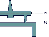
Submarine gate –A submarine gate is used in two-plate mold construction. An angled, tapered tunnel is machined from the end of the runner to the cavity, just below the parting line. As the parts and runners are ejected, the gate is sheared at the part. If a large diameter pin is added to a non-functional area of the part, the submarine gate can be built into the pin, avoiding the need of a vertical surface for the gate. If the pin is on a surface that is hidden, it does not have to be removed. Multiple submarine gates into the interior walls of cylindrical parts can replace a diaphragm gate and allow automatic de-gating. The out-of-round characteristics are not as good as those from a diaphragm gate, but are often acceptable.


